Tool
Flash the firmware v1.1.10 Release
Chrome or Edge writes it over the USB cable in about a minute, with the six steps and the safety wording on the page beside the button.
00 The build v1.1.10 Release
2026-10-15
One ESP32 touchscreen board, a USB cable and a browser is the whole shopping list. CYGM is an open-source CGM display for a sensor you already wear, and there is nothing to solder.

01 Parts
The cheapest CYGM that works is one display board plus a USB cable you already own. I add the speaker and the battery because I want them, not because the thing needs them.
Before you order anything, read this bit twice. The board is the JC2432W328C, and that trailing C is the whole ballgame. There is a resistive board sold under almost the same name, it looks the same in the photos, and my touch driver will not talk to it. No software fix, no workaround, just a $20 paperweight. So open the listing, find the word capacitive, and only then pay. This is the one way I know of to lose money on this build.
Parts required and optional for a CYGM build
Part · What it is for · Needed · Approx. cost · Where
ESP32 display board, JC2432W328C capacitive Required
The whole device. A 2.8-inch touchscreen development board with WiFi, USB-C and a microSD slot. Amazon
~$20
Mini speaker, 1 W 8 Ω, JST-PH 1.25 mm Optional
Plugs into the board's amplified output. I metered it peaking at 105 dB with the speaker fitted, and measuring sound is my trade. Without it the board still makes a noise, but a quiet one. Amazon
~$8
LiPo battery, 3000 mAh Optional
Portable use and riding out a power cut. The printed case is sized for it, and CYGM runs from USB without it. Its plug goes in the connector marked BAT, never the one marked SPK, which destroys the amplifier. Amazon
~$12
4x M3x10 button head screws Optional
Hold the two halves of the printed case together. Any hardware shop
~$1
USB-C data cable Required
Power, and the first firmware flash. It must carry data. You probably own one
n/a
3D-printed case Optional
An enclosure sized for the board and the 3000 mAh battery. MakerWorld
n/a
microSD card Optional
Optional CSV logging of readings, which you can read back later in the card viewer. Any small card
n/a
Prices are approximate. The links go to the exact items I built with. Buy the equivalent anywhere you like, with the one exception above: on the board, capacitive is not a preference.
02 Assembly
Two connectors, four screws, and a case if you want one. Fifteen minutes with a small screwdriver.
A lithium cell is the one part of this build that can hurt you. Treat it with the same care you would give any other lithium battery in the house, and if any of this makes you uneasy, skip the battery entirely and run the device from USB. It works perfectly well that way.
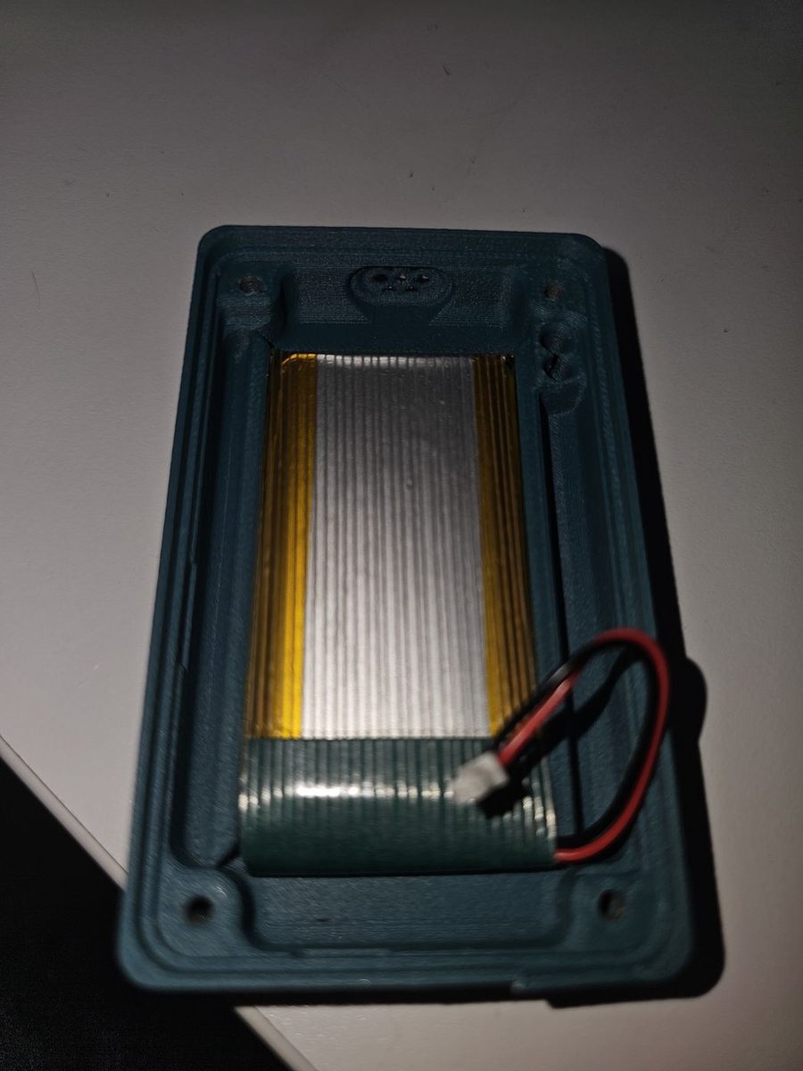
Snap the battery into the bottom of the case, with the wire routed towards the side with the buttons. It only sits one way round. This is the step that puts a lithium cell in your hand: the handling rules are in the box directly above.
Peel the protective film off the speaker and press it into the speaker slot. Push firmly, so the adhesive takes.
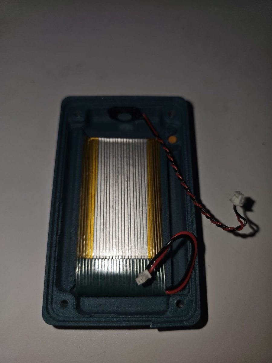
The speaker goes in SPK. The battery goes in BAT. Do not mix them up.
Putting the battery into the speaker port destroys the audio amplifier the instant you connect it. Not sometimes, and not recoverably. There is no fuse to replace and no setting to change. The board will still work, the screen will still work, and the speaker will simply never make a sound again.
Ask me how I know.
The two connectors look almost identical and they sit close together, which is exactly why this is worth a paragraph. The board tells you which is which in tiny white letters beside each one. Find BAT+ and BAT- for the battery and Speak for the speaker, and check them under a decent light before you push either plug home. The photograph below is that corner of the board, close up.
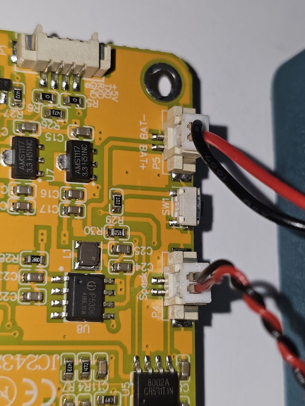
Plug the speaker into SPK and the battery into BAT, having just read the paragraph above.
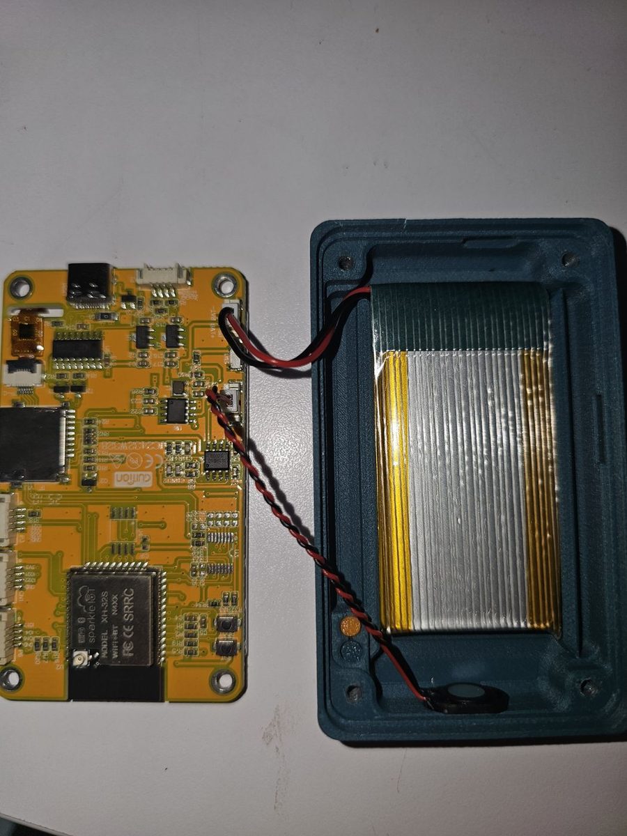
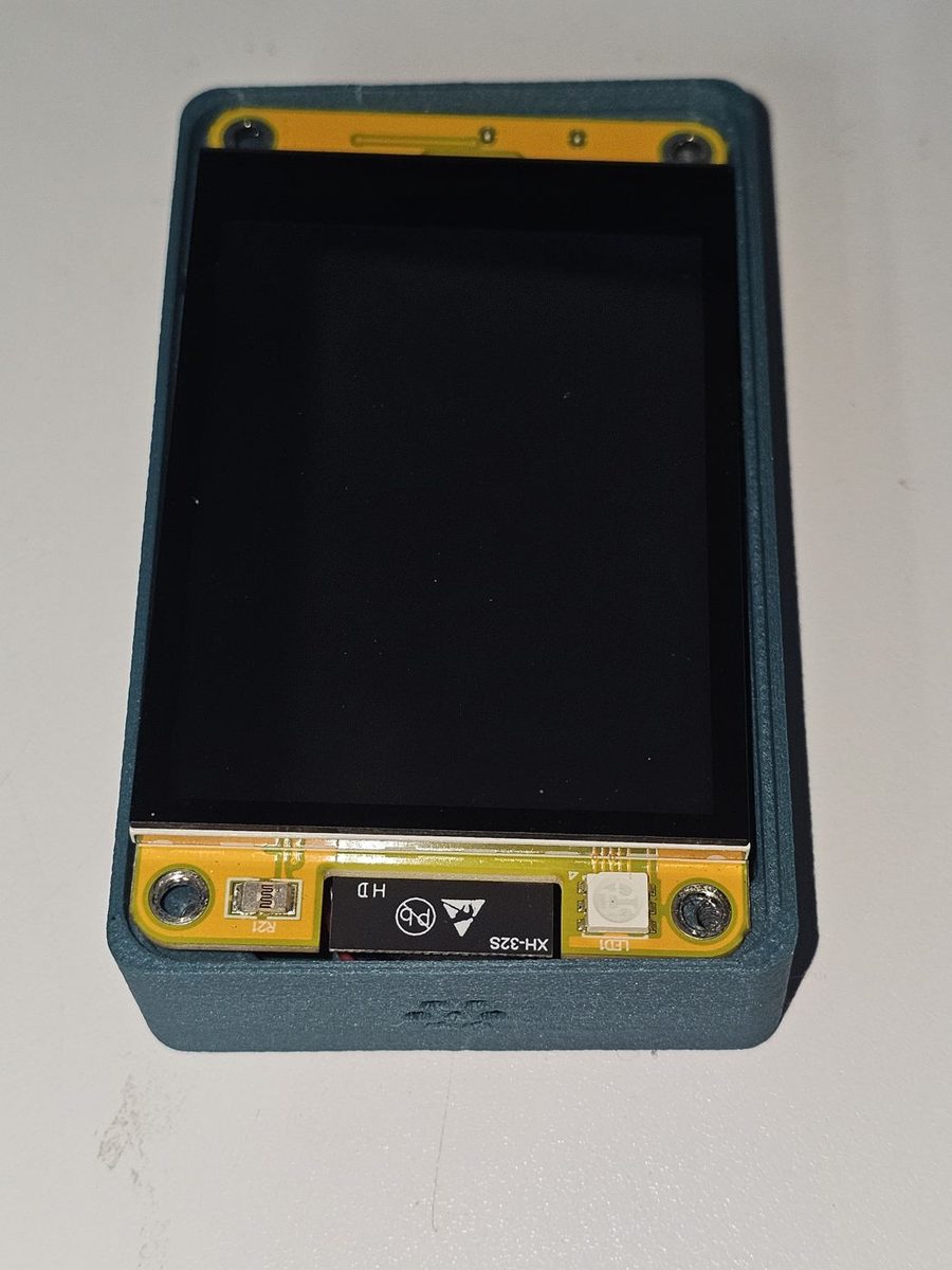
Lay the board into the base. Line the top up with the board; there is an indent for the status LED which makes it obvious when you have it the right way round.
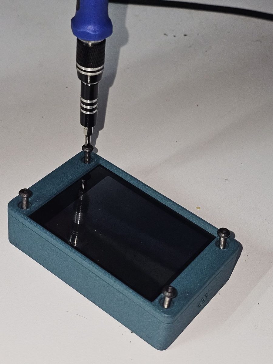
Screw the top to the base with the four M3x10 button head screws. Snug, not tight. It is plastic.
That is the whole build. Everything from here happens in software.
If you are printing the case yourself, the model is published here with my settings saved into the profile.
03 Firmware
Tool
Chrome or Edge writes it over the USB cable in about a minute, with the six steps and the safety wording on the page beside the button.
04 First run
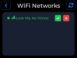
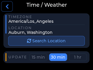
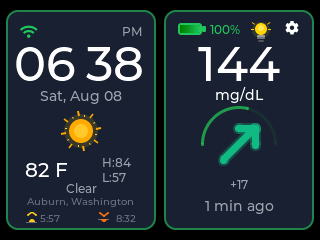
A freshly flashed device walks you through all of this on screen, one card at a time. If you would rather drive it yourself, everything below is in the settings gear.
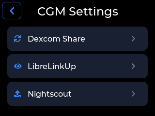
Each service has its own page: Dexcom Share, LibreLinkUp or Nightscout.
05 Specification
| Item | Detail |
|---|---|
| Board | JC2432W328C, capacitive touch variant |
| MCU | ESP32-D0WD, dual-core Xtensa, no PSRAM, roughly 320 KB of RAM |
| Display | ST7789 2.8-inch SPI LCD, 320 by 240, 16-bit colour, landscape |
| Touch | CST820 capacitive, over I2C |
| Audio | On-board buzzer, with an amplified output for the optional 1 W speaker |
| Power | USB-C, with optional LiPo battery |
| Storage | microSD slot, used for optional CSV logging of readings |
| Networking | 2.4 GHz WiFi. Every HTTPS client on the device verifies the server certificate |
| Data sources | Dexcom Share (G6, G7), LibreLinkUp (Libre 2, Libre 3, Libre 3 Plus), Nightscout |
| Updates | Over the air, into whichever of the two application slots is not running |
06 Source
Clone it, change it, ship your own build. That is the point of making it open source.
The firmware is one ESP-IDF application written in C, with a client per CGM service,
a hardware layer, and one file per LVGL screen. Build it with the ESP-IDF v5.5.2
toolchain: idf.py build, then idf.py -p PORT flash monitor.
07 Honestly
There is no sensor in this build and nothing goes near the body. It reads what your existing CGM already publishes to its own cloud service.
Not cleared or approved by any regulator, not clinically validated, and never the thing to dose from. Confirm on the official app or receiver first, always.
The official app has to keep running, because it is what uploads to the service my device reads from. This is a second screen. It is not a substitute for the first one.
08 Questions
No, nothing. The board turns up assembled, and the optional speaker and battery use plug-in connectors.
The JC2432W328C, the capacitive touch variant. The resistive board sold under nearly the same name has a different touch controller and will not work.
About $40 if you buy the lot, and roughly half that for the minimum build. The board is around $20, the speaker around $8, the battery around $12, all approximate.
No. Later firmware comes in over WiFi. You only need the cable for that very first install.
From your CGM service straight to the device. There is no CYGM account and no server of mine in that path.
09 Next step
Most of a DIY CGM display build is waiting for the post, so get the board moving and read the rest while you wait.
G6 and G7 through Dexcom Share, using a follower account.
Set up a Dexcom display →
Libre 2, Libre 3 and Libre 3 Plus through LibreLinkUp.
Set up a Libre display →
Any sensor your own Nightscout site already handles. Point the device at your URL.
Set up a Nightscout display →
Once yours is running, the device guide walks every screen, and the card viewer reads back the readings logged to a card.
CYGM is an open-source, experimental secondary CGM display. It is not FDA-cleared or FDA-approved, and it has not been clinically validated. It shows readings that have already travelled through your own CGM's app and cloud service, so it can lag, gap or fail independently of them.
Never use it as the sole basis for a treatment decision, and never rely on it as your only alarm. Always confirm on your prescribed CGM receiver or app before dosing or treating.